Installation of backlit display on the Casio CZ
--------------------------------------------------------------------------------
NOTE!
I decline all responsibility in installations as described below.
This is only a description of how I chose to do.
Installation as described below is done at your own risk.
--------------------------------------------------------------------------------
************************************************************************************************
* New updated installation instruction! Please read the text that is highlighted in red further down this manual! *
************************************************************************************************
The Casio LCD on Casio CZ-101, CZ-1000, CZ-3000 and CZ-5000 is of type HD44780 2x16 characters.
I chosed to buy my displays at Kjell & Co (www.kjell.com). They have two different models of the HD44780. One has a blue background with white characters (part no. 90 215) and costs 129 SEK (USD20). The other has a green background with black characters (art. no. 90 213) and costs 119 SEK (USD18). The instructions on this page is only valid for the display I bought from Kjell & Co.
Links to these two can be found here:
http://www.kjell.com/sortiment/el/elektronik/optokomponenter/lcd-displayer/lcd-display-p90215
http://www.kjell.com/sortiment/el/elektronik/optokomponenter/lcd-displayer/lcd-display-p90213
I chosed the blue screen because I thought it fit best with a "CosmoSynthesizer" :-)
I installed the display in two different CZ synths, a CZ-5000 and also a CZ-101. The photographs show the installation on a CZ-101 but I will also describe the difference as I did when I installed on my CZ-5000.
The original display has 14 pins. A bit confusing is that the earth wire is red and the power cord is white. If you turn the display so you have the backside up, pin 1 is on the far left and pin 14 on the far right. If you look at the new display it has 16 pins. This is because two of the pins are + and - to the backlight.
The pinout schematic looks like this:
| Pin no. | Function |
| 1 | Ground |
| 2 | +5V |
| 3 | Contrast adjustment |
| 4 | Register Select (RS). RS=0: Command, RS=1: Data |
| 5 | Read/Write (R/W). R/W=0: Write, R/W=1: Read |
| 6 | Clock (Enable). Falling edge triggered |
| 7 | Data buss Bit 0 (Not used in 4-bit operation) |
| 8 | Data buss Bit 1 (Not used in 4-bit operation) |
| 9 | Data buss Bit 2 (Not used in 4-bit operation) |
| 10 | Data buss Bit 3 (Not used in 4-bit operation) |
| 11 | Data buss Bit 4 |
| 12 | Data buss Bit 5 |
| 13 | Data buss Bit 6 |
| 14 | Data buss Bit 7 |
| 15 | V+ (backlight anode) |
| 16 | Ground (backlight cathode) |
Pin number three from the left is pin 1 in the table above. This means that the physical pin 1 on the display, is pin 16 in the table above. The physical pin 2 of the display is pin 15 in the table above.
I chosed to bridge the physical pin 1 to the physical pin 3 and bridged the physical pin 2 to the physical pin 4 because I'm lazy by nature and did not want to look up where on the board the plus and minus power was. This means that the backlight gets power from, pin 2 in the table abowe which is also the power supply to the circuit in the display.
In other words, the pin placement on the new display is as follows: 16-15-1-2-3-4-5-6-7-8-9-10-11-12-13-14.
The cables should sit exactly on the new display as they sat on the old with the difference that the first cable on the old display is soldered on the third pin of the new display (third pin is marked with number 1).
On CZ-5000, I decided to make a new connector because there was plenty of room on the main board of the synth. Then I was thus to leave the old display fully intact in case I would like to reinstall it.
On CZ-101, there was not enough space to mount the new contact, so I cut the wires to the old display and soldered together the original contact with the new cables to the display. I then covered the joints with shrink tubing so they don't cause a short circuit. It's not recommended to use insulation tape because it usually has the ability to glide. Remember to fit the heat shrink tubing on the wires before you solder them together or you will have to un-pin the connector to fit the shrink tubing.
Since the new backlight display is thicker than the old one, there will be a distance between the screw holes and the LCD. You can take a small plastic tube and cut and add as distance or you can do like me, screw anyway. The holder will then bend a little so you have to be careful so you do not screw too tight.
It is also important to add tape to the side of the bracket that is close to the "wires" to the backlight otherwise you will short cut the LCD. I also chosed also to tape the top side which lies against the circuit board so the metal should not short out any components.
---------------------------------------------------------------------------------------------------------------------
NOTE!
* If the contrast is too high and the display-text is hard to read, insert a 2.2 kOhm resistor between the blue wire and pin 3. That would result in a better contrast.
* I have also recieved feedback that it is necessary to add a resistor to the backlight + line to extend the lifetime of the new display.
Make a jumper from Pin 1 (-) to Pin 16 and insert a 65 Ohm resistor between Pin 2 (+) and Pin 15.
I haven't done this to my installation yet so I advice you to try this and check the function before you assemble the synth to make sure the display work as it should.
----------------------------------------------------------------------------------------------------------------------
Good luck with the installation!
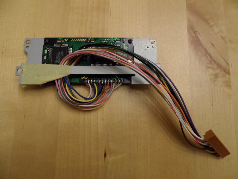
This is the original display when it is removed
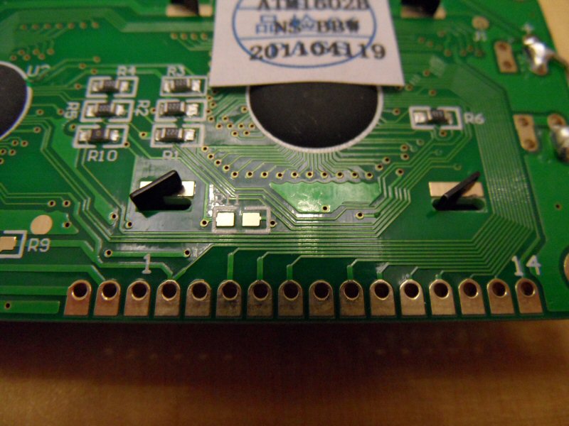
The new display. Note that pin 1 is the third pin from left.
For CZ-5000 I made a new contact by glue together a 10-pole and 4-pole connector. I had to carve off the rails because they don't fit the synthesizer plug.
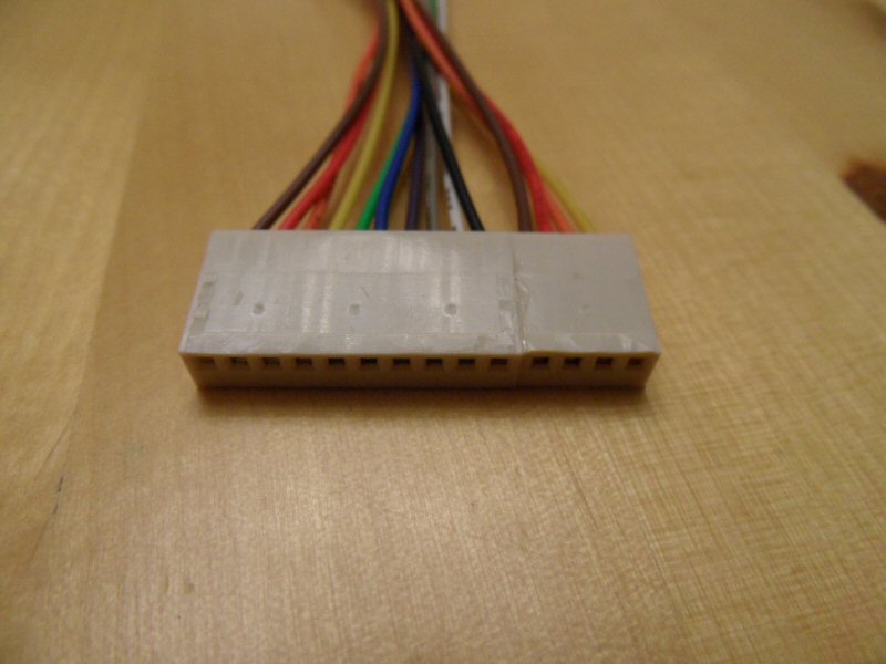
The pin openings are slightly larger on my new contact but it worked. You can add a small amount of melting glue when connecting plug if it is loose.
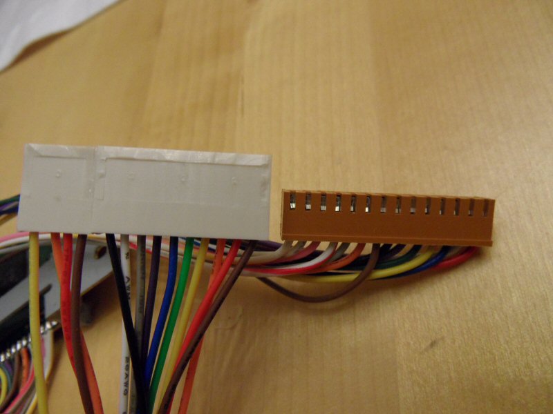
Apparently, the new connection is higher, but it doesn't matter for the CZ-5000 (it doesn't work on CZ-101 though).
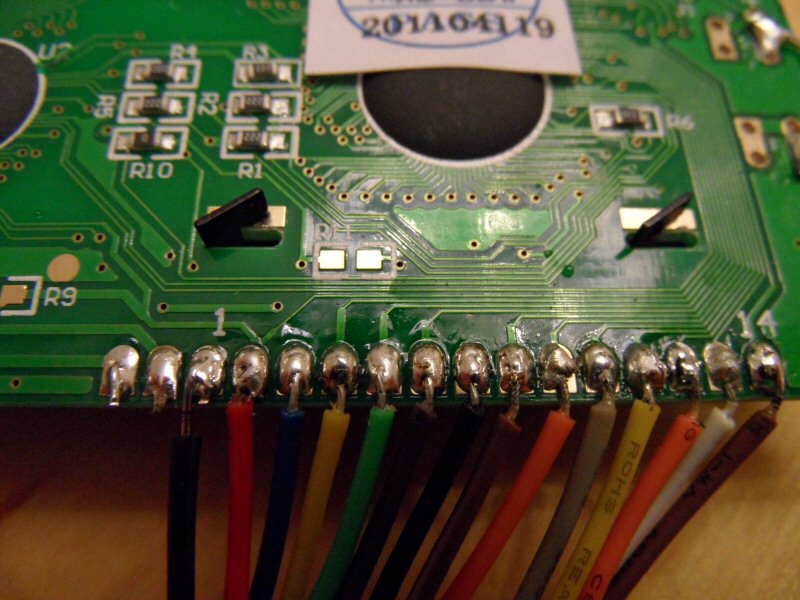
New cables are soldered to the new display. I chosed red to + and black to -.
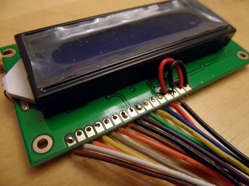
This is the result when you turn the display. Note that I have jumpers between + and - to the backlight.
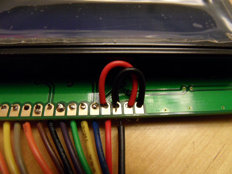
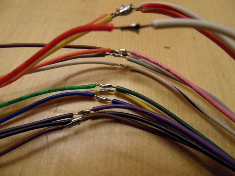
Jumper close-up.
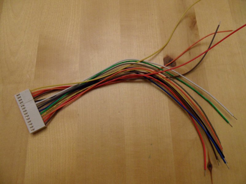
And this is how it looks from the other side ...
The cables to the display is now soldered with the cables to the original contact (I had to cut the original cable harness because I needed the original contact). NOTE! Do not forget to cover the solder with shrink tubing so they are not shorting.
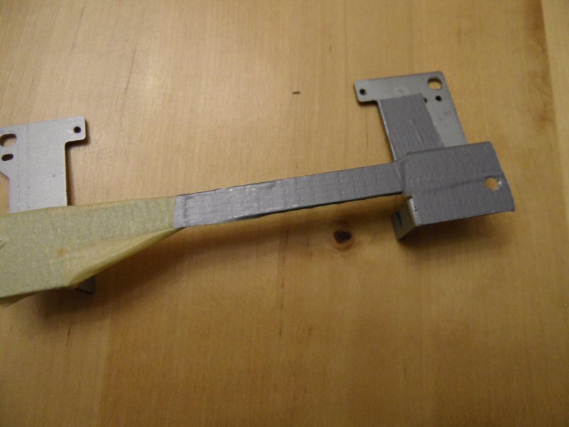
The bracket for the display is now taped. I taped the top because this is facing the circuit board (the bracket is now a little higher because the display is higher). It is also important that the right side of the holder are taped around so that no connectors to the lights are short-circuited.
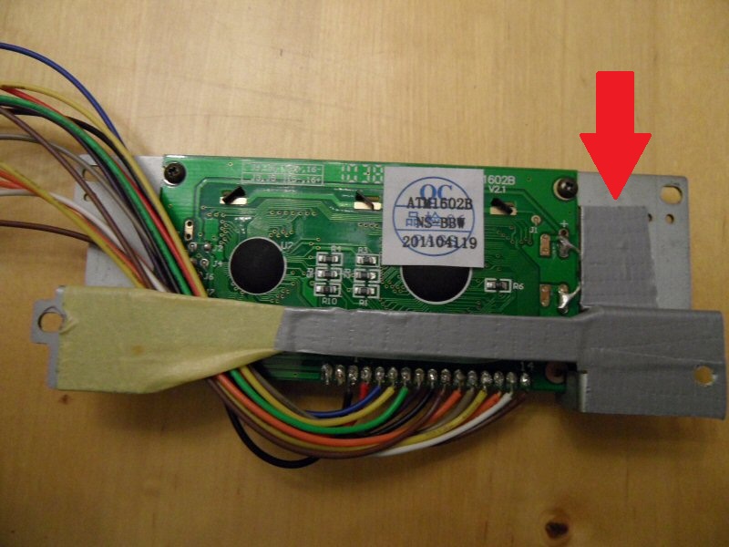
Now the display is mounted in the holder and you can clearly see why it is important to tape the right side.
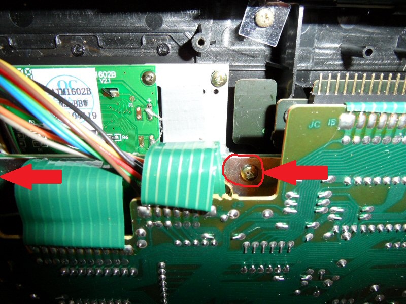
It is advisable to loosen the two screws holding the PCB slightly so it fits a little loose in the end because the new display is higher.
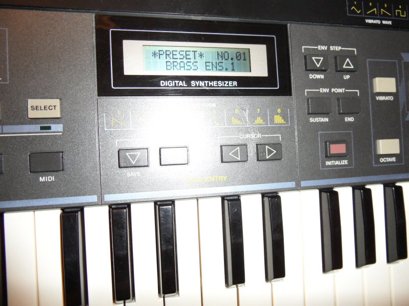
Here is the synth before surgery ...

... and this is how it looks after the procedure. I can guarantee that it looks much better in real life. The camera had the ability to compensate for the strong lighting in the display.